
The heart of the DÆ v4.2 stepped attenuator is the ladder level printed circuit board. On one side of the printed circuit board is an array of resistors that attenuate the audio signal. On the other side is a series of 24 reed switches. The desired attenuation is selected by positioning a magnet adjacent to a particular reed switch. A stepper motor is used to precisely position the magnet.
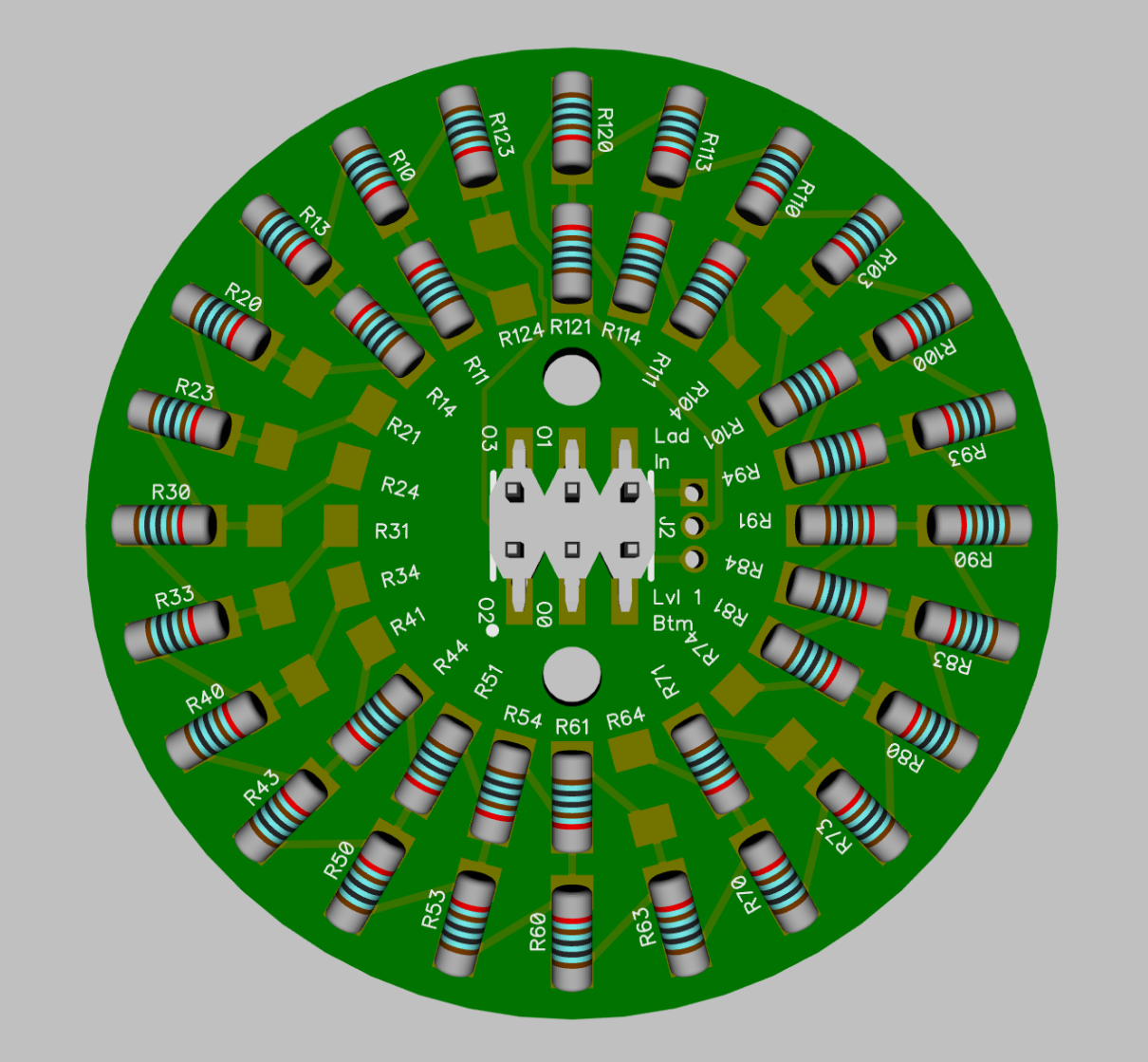
DÆ v4.2 stepped attenuator ladder level printed circuit board resistor array side.
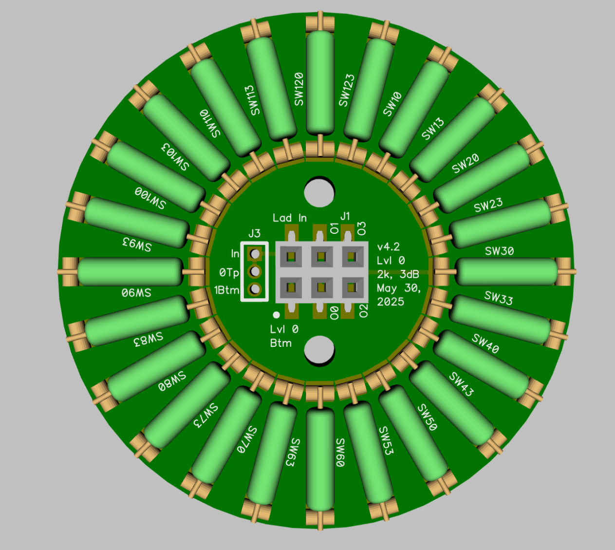
DÆ v4.2 stepped attenuator ladder level printed circuit board reed switch side.
My initial idea was to position the magnet directly inline with a particular reed switch to select one of 24 gain levels. The reed switches on either side of the selected reed switch should be off. As the magnet is rotated from one gain level to the next, there should be an angular position where two reed switches are on at the same time. Once the magnet stops next to the desired reed switch, there should only be one single reed switch on.
This happened the majority of the time but every so often two reed switches would be on even after the magnetic stopped moving. This would cause a gain error which is definitely not acceptable for a high precision stepped attenuator.
Both the desired action and the erroneous action are shown in the animation below. Notice that when the magnet comes to rest next to reed switch SW20, reed switch SW13 is still on which is wrong. The other gain positions are working properly. The animation only illustrates the first six positions but the magnet can move to all 24 positions from SW123 at low volume to SW120 at full volume.
An animation of the desired action and the erroneous action when reed switch SW13 remains on after the rotating magnet comes to rest adjacent to reed switch SW20.
I struggled to get this idea to work but after a while I suspected that the tolerance in magnetic sensitivity of individual reed switches meant that I could not guarantee that only one reed switch was active when the magnet came to rest. I could not simply increase the separation between the reed switches because that would require increasing the size of the ladder level printed circuit board - I didn’t want to do that because in general I am trying to make the attenuator smaller with each iteration. I also need to guarantee that two reed switches are on when the magnetic moves between positions. This is the make before break action. If there are angles where no reed switch is active the attenuator would go open circuit producing a click in the audio signal. This could not be tolerated.
So if you can’t beat them, join them.
I revised the stepper motor program so that the magnet comes to rest directly between two reed switches at each attenuation level. This solved the problem and now all the gain levels are reliably achieved.
The revised magnet positioning strategy is shown in the animation below. The animation only illustrates the first six positions but the magnet can move to all positions from SW123+SW10 at low volume to SW113+SW120 at full volume.
Animation showing magnet coming to rest between two reed switches ensuring two and only two reed switches are active at each attenuation position.
To put a bit of math to the operation - the reed switches are positioned at fifteen degree intervals around the ladder level printed circuit board. In the initial plan the magnet came to rest directly inline with a single desired reed switch; so the magnet was zero degrees away from the desired reed switch. At rest the magnet was also fifteen degrees away from the two adjacent reed switches. With this angular separation the adjacent reed switches are usually off but occasionally due to reed switch magnetic sensitivity tolerances one of the adjacent reed switches would still be on. The result is a gain error for the attenuator.
With the revised action, the magnet comes to rest at a point 7.5° from two adjacent reed switches and both are active. This happens reliably. At the same time the magnet is 22.5° from the next two reed switches and even with magnetic sensitivity taken into account they will be off - reliably.
The eagle eyed reader will notice that there are now only 23 valid positions for the magnet because the whole resistor ladder is shorted out if the first and last reed switches in the ladder, SW123 and SW123 respectively, are closed at the same time. This would not be good for the amplifier driving the attenuator. To get back to 24 steps, the last step involves positioning the magnet between reed switches SW123 and SW10 which is the lowest gain setting and engaging the mute feature of the attenuator.
Et voilà - problem solved. If you can’t beat them, join them.