
Below is a description (long awaited) of the DÆ Modular Stepped Attenuator v3.0.

v3.0 Attenuator Front
The volume level of the v3.0 Attenuator is selected using a series of reed switches arranged in groups of twelve and stacked in levels. A maximum of eight levels are possible but so far three levels or 36 steps has been more than adequate to provide smooth volume level selection. An individual step is selected by a stepper motor positioned magnet. This unique design provides a quiet, very accurate, remote controlled attenuator.
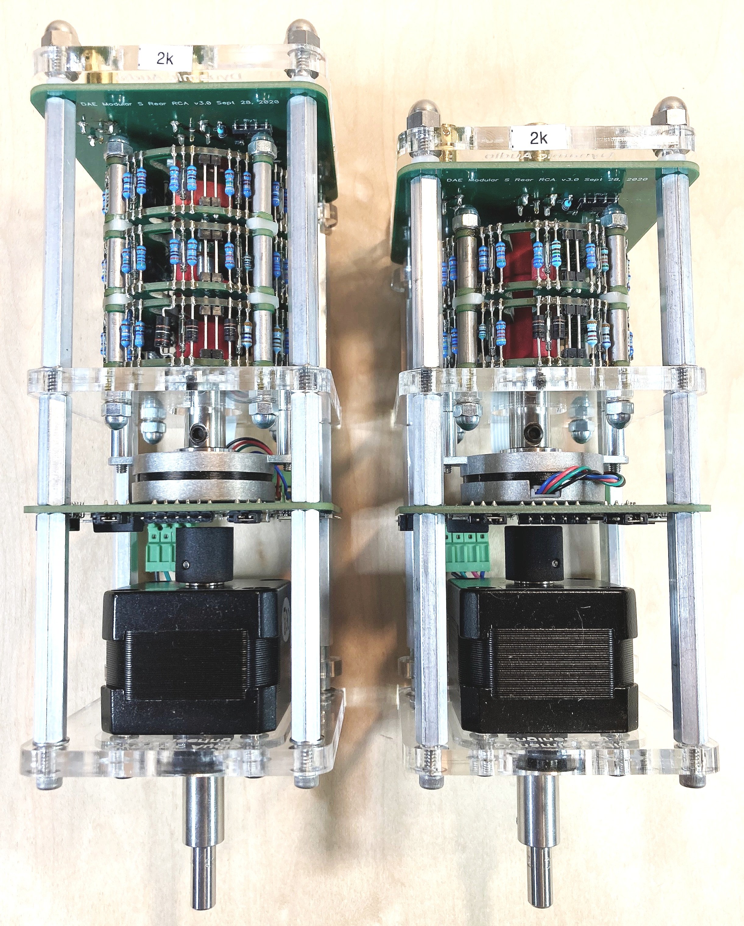
Comparison of three level (left) and two level (right) attenuator.
The photograph above shows a three level (left) compared to a two level (right) attenuator. The three level attenuator has a total of 36 steps whereas the two level level attenuator has a total of 24 steps. The attenuator can be described as a number of sections. Starting from the bottom of the image the sections are:
The 1/4” diameter knob shaft;
The knob stepper makes the volume control motor operated and provides the excellent feel of magnetic damping when the knob is turned by hand. Another unique feature of the v3.0 attenuator is the knobs of the left and right attenuators are maintained at the same angle under motor control. If either the left or right channel knob is rotated, the knob on the other channel is automatically moved to the same angle. Likewise, when the remote control is used to adjust the volume, both knobs move in unison;
The knob position shaft magnet holder. A magnetic angle sensor is used to continuously read the angle of the knob shaft;
The “control” printed circuit board (PCB). The control PCB includes the Bluetooth radio enabled microcontroller which is the brains of the attenuator. Two Trinamic stepper drivers with StealthChop mode to ensure silent operation of the knob and ladder stepper motors. The magnetic angle sensor to continuously monitor the knob angle. The software in the microcontroller controls all functions of the attenuator and provides the digital logic output for source selection (one of four). Another interface supports the addition of a power switch and source selection switch(es);
The ladder stepper rotates a “yoke” supporting the magnets that actuate the appropriate reed switch to select a particular attenuator step. Another magnetic holder is attached to the end of the ladder stepper shaft to provide continuous monitoring of the ladder stepper angle using a second magnetic angle sensor;
The ladder level include twelve steps each. An individual step includes two 1% precision resistors in parallel and a reed switch. The two parallel resistors provide superb level matching between the two channels and great flexibility in specifying the level at each step;
The rear PCB includes the ladder stepper magnetic angle sensor, an input RCA jack, an output RCA jack, a “muting” circuit and an output header for source selection. The muting circuit is part of the system ensuring silent, glitch free transitions between steps.

v3.0 Attenuator Level
The photograph above shows a single level of the v3.0 attenuator. Around the perimeter of the level are twelve steps consisting of a reed switch flanked by two 1% precision resistors. When the magnetic attached to the yoke is adjacent to a step, the reed switch closes and that particular step is selected. The ultra-miniature dry-reed switch is hermetically sealed in a gas filled envelope to ensure a long life of 100,000,000 operations minimum. A reed relay is energized to select the appropriate level for a given volume setting.

v3.0 Attenuator yoke in operation.
The video above shows the v3.0 attenuator with the ladder levels removed so that the yoke (red part) can be seen to rotate to precise angles as the volume control knob is turned. Note that the yoke includes two magnetics so that two ladder levels can be used.
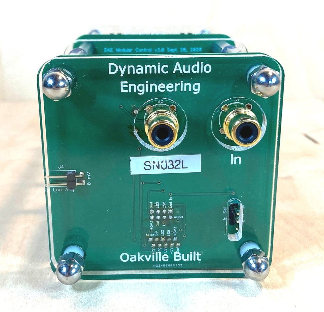
v3.0 Attenuator Rear.
The photograph above shows the rear of the v3.0 attenuator. There is an RCA connector for the attenuator input and a second RCA connector provides the attenuator output. There is a three pin header that provides a digital (3.3 V logic) output of the source selection. The other two pin header provides an analog output of the ladder angle that is used during the factory calibration process.

v3.0 Attenuator Bottom.
The photograph above shows the bottom of the v3.0 attenuator. There are four 6-32 threaded inserts that provide mounting points for the attenuator.
v3.0 Attenuator pair in action.
The video above shows that the knobs of two v3.0 attenuators remain synchronized. The cable between the attenuator is only for power; a Bluetooth radio link between the attenuators keeps them synchronized. The same Bluetooth radio provides remote operation of the attenuation using either the dedicated remote or the iOS app.
The following blog posts describe the development of various aspects of 3.0 Attenuator: May 9th, 2019, July 11th, 2019 and December 13th, 2019, July 2nd, 2020 , November 29th, 2021 and December 13th, 2021. Please see these Blog posts for more details.