Sorry for the Long Delay...

It is hard to believe it has been one month since my last post but I haven’t been slacking!

There is been some bad weather in Canada with snow and ice storms and, yes, that has slowed the testing and prototyping work down. In particular it takes and extra day or two for shipping (feels more like a week longer). I finally received the top and bottom covers for the remote and it came together nicely.

The remote completed!

The remote completed!

I received more parts for the glass and acrylic vacuum enclosures. I found some really nice Brass Heat-Set Inserts for Plastic at McMaster-Carr that will allow me to use the sleeve valve on the acrylic enclosure. The inserts are heated with a soldering iron and while hot pressed into the acrylic. This worked quickly and very well but of course I will need to seal the joint with Torr Seal epoxy if there is any hope of it being vacuum tight.

I completed testing a very quiet stepper more driver IC from a German company called Trinamic. The IC has a mode called StealthChop which is advertised to make the stepper motor operation “completely noiseless”. It is truly quiet! I am now testing the last miscellaneous auxiliary circuits and will soon be completing the schematics and printed circuit boards for the v2.2 version of the stepped attenuator.

I am so looking forward to pulling the v2.2 version together.

More on this later…

Off to the Races

DÆ Remote

I received the printed circuit board for the remote and had time to populate it. I also had time to advance the firmware to a near final version. I received the laser cut acrylic top and bottom but I am still waiting for the 3D printed covers. I should have the covers by the end of the week and will add a better description to the DÆ Remote product page when I get that far.

I am very happy with the results. It looks so cool that my wife wants one even though she doesn’t need it. High praise in anybody’s book. Actually she asked if I can turn the industrial design into a phone. Another future project?

The remote uses capacitive touch technology so the main body is only 6 mm thick! Using proximity sensing it lights up when you go to pick it up. Turns out this is a fun feature in a brightly lit room but really works well in a dimly lit room; and a lot of serious listening in done in a dimly lit room. The remote has a light sensor so the intensity of the back light is tailored to the ambient light in the room. This seems like a small detail but I need to add it to my pre-amp design because the indicator lights on the pre-amp are good during the day but far too bright and distracting in lower ambient light. The lithium battery is charged by plugging the remote into a USB port. I expect the remote will run for a few months on a single charge.

The remote is coming together.

The remote is coming together.

Vacuum Testing, Vacuum Testing and More Vacuum Testing

I think I have now solved all my major design issues with the glass vacuum chamber. The sleeve valve, improved cable feed through and absolute vacuum sensor all work well. The absolute vacuum sensor is on the PCB inside the vacuum chamber in the picture below. Using this sensor, I can draw a vacuum through the sleeve valve, close the sleeve vale and plug its port while still getting a vacuum measurement. This design eliminates the external vacuum tubing which is a potential source of leaks.

I have now tested for almost a month with very, very little pressure change. Maybe only the small amount of off-gassing from the components is contributing to the tiny decrease in vacuum I can measure. The absolute vacuum sensor saturates as all the air is evacuated and the leak rate is now approaching the limit of what I can measure. Perhaps it is time to add a “getter” material for the next bit of performance improvement.

Long-term vacuum testing including glass enclosure, sleeve valve and absolute vacuum sensor.

Long-term vacuum testing including glass enclosure, sleeve valve and absolute vacuum sensor.

Sleeve Valve Plus

Happy New Year.

Sleeve Valve - The picture below shows a new sleeve valve I am testing. The sleeve valve is much smaller than the ball valve I have been using. I have high hopes this will give me the ability to evacuate the chamber, close the sleeve valve and not need to re-evacuate for a long period of time. I also think the sleeve valve is very well built and looks appropriate for the job.

Other work - I have done a lot of testing on the new cable feed through described in my December 31st post. It has a very low leak rate indeed. I also have been testing an absolute vacuum sensor that is installed inside the vacuum chamber. This sensor eliminates the changes in barometric pressure that contaminated the readings I get from the differential vacuum sensor in my vacuum test set-up. Between the sleeve valve and internal vacuum sensor, I can eliminate all the Viton tubing external to the enclosure so I expect an even lower leak rate. Finally I am getting a solution I am happy with.

One more thing - I just started testing a version of my acrylic vacuum enclosure with improved optically clear solvent welded joints and thicker end plates. The new end plates are 9 mm thick instead of 6 mm thick.

More on all this later.

Sleeve valve near centre of image.

Sleeve valve near centre of image.

New Cable Feed Through

Near the center of the image below is the new cable feed through. It has solid metal pins instead of a flex cable with insulation. The insulation on the flex cable is one of the expected sources of vacuum leak (see December 7th post). The metals pins are surrounded by white Agilent Torr Seal epoxy. This epoxy is specifically formulated for vacuum applications with very low off-gassing.

The epoxy should finish curing by tomorrow morning and I will test it. I have high hopes.

New cable feed through.

New cable feed through.

A Little More Information

For a while I have wanted to put one of my acrylic vacuum chambers under water to determine the location of any air leaks. Good news is the solvent welded joint between the acrylic cylinder and the end flanges is leak free. I am still studying techniques to build an optically clear joint at this point but this would be a cosmetic improvement only because the joints already appear to be air-tight. More on this later.

But, I found a small leak at the viton seals. The end plates are attached to the flanges on the acrylic cylinders using four fasteners as seen in the picture below. The end plates are 6 mm thick acrylic which flex just enough that there isn’t sufficient pressure on the viton seal at the mid-point of the end plates. I have ordered 9 mm thick end plates to test if this solves the problem. I’ll provide updates later.

With thicker end plates and a better feed through as described in my December 7th post perhaps there is life in the acrylic version yet. Parts for the improved feed through are being couriered to me as write this blog.

Other progress over that last two weeks includes testing a breadboard version of the Microchip Technology AT42QT2120-SU capacitive touch sensor integrated circuit. I plan to use this for a remote control. This will be an alternative to using the iOS remote described elsewhere on this website. Again more on this later.

Acrylic vacuum chamber under water.

Acrylic vacuum chamber under water.

Progress on Two Fronts

In my November 26th blog post, I described a slow vacuum leak that I thought was due either to reusing the Viton seals (black ring in photo below is rear seal) or a leak in my vacuum testing apparatus. It turned out to be something altogether. After testing all the components individually, I convinced myself the leak is in the cable feed through.

Near the centre of the picture below, there is a flex cable passing through an opening in the aluminum plate. The opening is sealed with epoxy. I speculate that flex cable insulator is just porous enough to allow a small amount of air to enter the vacuum chamber.

A commercial vacuum chamber cable feed through is very expensive but one feature they seem to have in common is metal pins encased in epoxy. The pins don’t have any electrical insulation. I think the electrical insulation on the flex cable is the weak link. My next step is to redesign the cable feed through to use uninsulated metal pins.

As a side note, I use the same cable feed through on the acrylic version of the enclosure so after I redesign the cable feed through, I will test it on my acrylic enclosure design - there may be life in the acrylic version yet.

Rear aluminum plate of vacuum chamber showing flex cable surrounded by epoxy.

Rear aluminum plate of vacuum chamber showing flex cable surrounded by epoxy.

My other progress is with the frequency response testing of DÆ Phono Preamp v2.0. In my November 30th blog post, I described the fine tuning of the RIAA filter capacitors using a B&K 880 Precision LCR meter. Following fine tuning the filter capacitors, the filter matches, the ideal RIAA response to within 0.11 dB from 20 Hz to 20 kHz and within 0.03 dB from 50 Hz to 20 kHz. The low frequency roll-off is caused by the DC blocking capacitor and could be further improved with a larger capacitor. The measurement is 0.03 dB may be a limitation of my measurement process. Next, I will look to improve my measurement process.

DÆ Phono Preamp v2.0 Fine Tuning

This week I received a new B&K Precision 880 LCR meter. This meter is capable of measuring capacitors, inductors and resistors with an accuracy of 0.1%+2 digits.

A phono preamp RIAA filter requires two resistors and two capacitors. The accuracy of the RIAA response is sensitive to the accuracy of the components. 1% tolerance resistors are readily available and some 1% tolerance capacitors are available. To get a more accurate RIAA response than what is possible with 1% tolerance parts in common series values (E96 resistors for example), multiple resistors and capacitors can be used in series and parallel combinations. As an example if two equal value components are combined to make the desired resistor or capacitor, the effective tolerance is improved by 1/√2; so two 1% parts make a 0.7071% tolerance combination.

My resistor tester project provides the measured tolerance statistics for 1% metal film resistors to aid in understanding the likely results of combining resistors.

As an alternative to combining several parts, the DÆ phono preamp V2.0 uses two capacitor multiplier circuits. The capacitor value of the capacitor multiplier circuit can be trimmed using a potentiometer. Using the B&K Precision LCR meter the capacitors can be trimmed to 0.1%. It would take one hundred 1% components connected in parallel (or series) to achieve a 0.1% tolerance component.

Next I will test the frequency response of the phono preamp to confirm the capacitor fine tuning provides the desired very accurate RIAA response.

Fine tuning phono preamp with B&K Precision 880 LCR meter.

Fine tuning phono preamp with B&K Precision 880 LCR meter.

Ladder Attenuator Installed - Its Very Quiet But..

I added a sample relay switch ladder attenuator into the vacuum chamber. It is very quiet but there appears to be a small leak. The leak may be caused by re-using the Viton seals a second time or possibly a leak in my vacuum test set-up. The leak is very tiny but I still need to track it down.

One step forward, two steps back…

Relay Switched Ladder Attenuator installed in glass vacuum chamber.

Relay Switched Ladder Attenuator installed in glass vacuum chamber.

Success with Vacuum Test

Success!

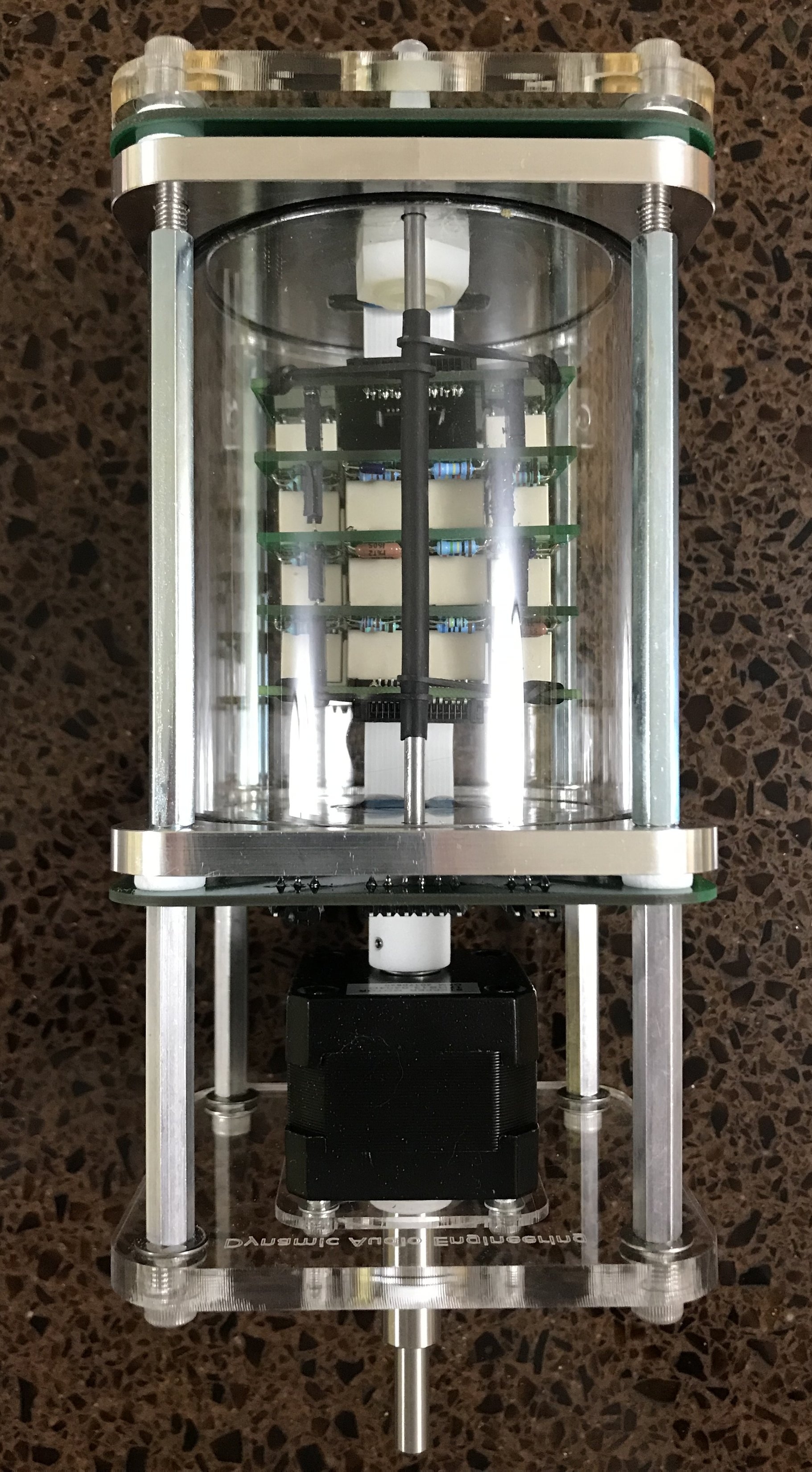
After many trials, the attenuator pictured below successfully holds a vacuum for 24 hours and likely much longer. The attenuator has a glass cylinder and aluminum end plates. The end plates include the flex cables openings to allow electrical connections between the vacuum chamber and the control and connector printed circuit boards.

Next step - build a new set of relay switched ladder attenuator sections.

Successful vacuum test on this attenuator including glass and aluminum vacuum chamber.

Successful vacuum test on this attenuator including glass and aluminum vacuum chamber.

Initial Post

First post! I hope to add more posts as I got along.

Currently working on aluminum/glass version of vacuum enclosure for the stepped attenuator.

The acrylic version had too high a leak rate to allow the vacuum to last for months/years. Aluminum and glass are much better vacuum materials. Glass is 3 mm thick and aluminum end caps are 6 mm thick. Laser cut Viton seals are used.

Prototype aluminum/glass version of stepped attenuator enclosure

Prototype aluminum/glass version of stepped attenuator enclosure

Prototype acrylic version for comparison

Prototype acrylic version for comparison